Guzzler Drivetime Methodology
Drivetimes calculate how far can be travelled in a specified period of time from a chosen location taking into account the underlying road network and varying road speeds. For example, understanding how far can be travelled from a particular point can be useful in determining service coverage from a central base, in terms of vehicle range. Ambulance services, for example, are able to position units strategically for both maximum coverage and efficiency. Response times can be accurately predicted for any location, and maps can be produced indicating at a glance which units are best placed to respond to a need in a particular location.
This guide explains how Guzzler uses road network data, including detailed street mapping, to produce very accurate results.
Driving speeds for the different types of road are contained within a settings file, which is found in your data product's Guzzler install directory.
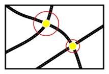
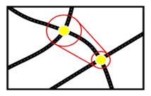
Nodes are marked in yellow, local roads in black, motorways in blue. Guzzler calculations, which are not visible to the user, are shown in red.
Nodes are the ‘joints’ of the mapped road network. Nodes usually correspond to junctions, intersections and access points we can identify. Node segments are the sections of road between the nodes. Nodes are up to .25 miles long. They are of varying length and each has a driving speed attributed to it. All segments (including those terminating in a dead end) can end at the beginning, mid node or at the end of a node.
A start point is chosen by the user. This can be any mapped object coming from a spatial field in a file input or new Map Input spatial field. Typically this is from a geocoded street address.
The results of a Drivetime trade area radius calculation are displayed as a Polygon. This is a shape in a map layer showing how far can be travelled for a specified distance or time specified by the user.
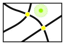
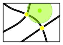
From a specified Start Point, Guzzler looks for nodes within the initial search radius.
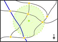
The initial search radius is a circular area around the Start Point. The size of this area can be changed in the settings file. By default, the initial search radius is 2 miles.
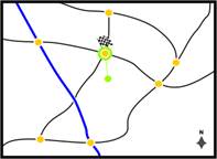
If there are nodes within the initial search radius, then the optimal node (Allows the furthest travel) is where the road network is joined. If multiple nodes fall within the initial search radius, then optimal node is chosen, the one which will travel on the fastest and furthest in the allotted time. The new methodology starts the calculation from the actual point and not the node start so a true calculation including potential off road time is calculated.
Some special-case logic is invoked when the outbound segments from nearest node are all one-way (e.g. on a highway. The new methodology now takes into account limited access roads and one ways.
In rare cases it is possible that no node is found within the initial search radius and therefore the road network is not joined. This is explained on.
Time taken to reach the first node is now included in the calculation and the time to reach the end point.
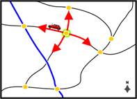
The road network is traced outwards from the nodes to find all the nodes reachable within the available time, subject to the varying speeds of different road segments and road network class.
Ferry routes are treated in the same way as road segments, and have speeds associated with them in the same way.
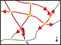
For each node reached, Guzzler calculates the remaining Drivetime and then looks again to see if any further nodes are reachable. This process is repeated for every node reached.
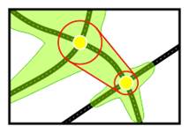
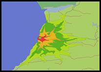
As the Drivetime calculation develops, we can see how different road speeds affect the shape. Faster roads produce longer tapering polygon ‘arms’, while those generated from slower roads are shorter and thicker.
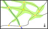
When no further nodes can be reached within the chosen Drivetime, any remaining time is added at Off-Road Speed (set at 2.5mph in the US). Remaining time is also added laterally from every node reached in the Drivetime creating the Off-Road Buffer, and the Drivetime Polygon is drawn. This will now be explained in more detail.
The purpose of the Off-Road Buffer is to simulate leaving the road network from any point in the Drivetime. For example, there may be areas which are drivable but not covered by the road network, such as car parks, private land and some rural locations.
Without the buffer, the results of a Drivetime calculation would contain only a list of reachable nodes and road segments.
When a node is reached, the Off-Road Buffer distance is calculated by multiplying the Off-Road Speed by the remaining Drivetime. This value is then added laterally from the node in all directions, forming a circle around it
Graphic representation
These circles are not displayed but are used to construct the Drivetime Polygon.
The outline of the polygon is drawn around the outer edges of these circles.
The shape of the Drivetime Polygon is created from these connecting lines. From any point on a road segment the Off-Road Buffer provides an accurate indication of the Off-Road Drivetime.
A minimum permitted value for the buffer is specified which prevents the polygon becoming too narrow.
In rare cases it is possible that no node is found within the initial search radius and therefore the road network cannot be joined.
The initial search radius may need to be increased in these cases because:
- The initial search radius has been set too low for general use, or
- The particular geography of the surrounding area means there are unusually few nodes.
In these cases, Off-Road Speed is used to generate a Distance Ring around the start point.
This Distance Ring shows how far from the start point can be travelled at Off-Road Speed. As the rate of travel is not modified or interrupted in any direction by variations in route or road segment speed, the Drivetime Polygon produced is a circle.
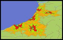
A range of Drivetimes can be produced for a single start point to show more clearly the effect of varying road speed. The result is a group of nested polygons.
How a Drivetime polygon grows over time can be as important as any single result and Drivetime Ranges can be used to visualize that development.
Ranges are specified in minutes and are formatted like this: “1-5, 5-10, 10-30”.
In a single calculation, a range of Drivetime Polygons can be generated around a number of different start points.
In the case of driving over large distances once the threshold is met only class 2 road networks will be used. This is specified so that only the fastest networked class 2 roads are used. The threshold can be changed in the xml if a user would like to jump on the quicker roads sooner.
Once all nodes are found to start a drivetime multiple potential start nodes will also be utilized within a multi start distance multiplier
In this way all good quality starting nodes are searched for which be of better quality than the first node which is found.
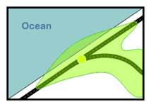
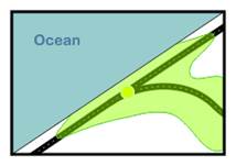
Because of the way the Off-Road Buffer is calculated, part of a Drivetime Polygon may extend into the ocean, despite it being inaccessible via the road network.
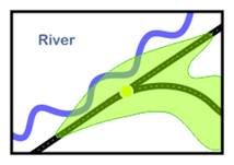
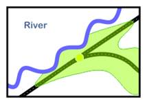
It is also possible that the Off-Road Buffer may be large enough to completely cross a body of water, falsely indicating that the land beyond is accessible in the Drivetime. This is sometimes the case where a Drivetime Polygon is close to a river.
Unless there is a bridge, or a ferry route, it should be clear to the user that this is a false interpretation. There are several ways to correct this:
It is good practice to ensure that layers containing oceans, lakes and rivers are situated above those containing Drivetime Polygons by arranging the layers in the table of contents taskbar.
This is the simplest way to ensure that the DrivetimePolygon does not appear to extend into a body of water, and is advisable if clipping has been carried out on any polygons.
In the case of a polygon appearing to completely cross a body of water, bisecting or clipping the polygon may be necessary.
In this way, the portion that is not reachable by road can be deleted. Two small portions of the Drivetime Polygon have been removed.
The Off-Road Speed specified in the settings file can be adjusted to change the size of the Off-Road Buffer. It may be possible in this way to avoid the need to clip the polygon. The minimum permitted value for the buffer can also be changed.
It is important to bear in mind that DrivetimePolygons which extend into a body of water will not produce distortions when creating reports. Counts are based on objects encompassed by the polygon, and not the polygon itself.
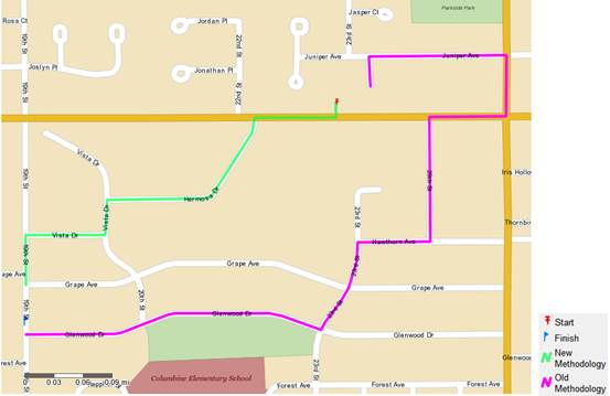
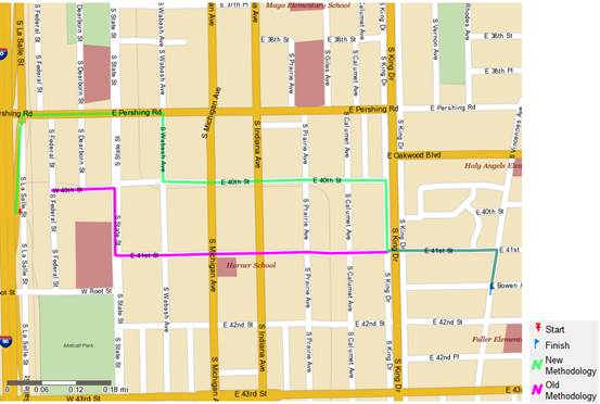
The new methodology of the drivetime shown in Green is the most accurate in that it is able to start mid node compared to the old methodology which must find the closest beginning or end node.
The Start point is located on a one way road and therefore the old methodology will teleport to non-one way start node and will then begin its drive time calculation, which allows it to reach its destination sooner. The New Methodology recognizes the one way road and is able jump onto it to start its drive time which leads to reaching the destination in a longer more realistic drive time.
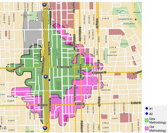
The resulting trade area will be affected by the limited access roads as well, as shown in the diagram below of the 3 minute trade area around the same start point above renders different trade areas affected by the limited access roads. The new methodology is unable to travel quite as far as the old methodology, but is more accurate.